
Metals and Alloys: Slides
H. K. D. H. Bhadeshia
Microstructure of Pearlite
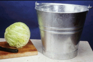
A colony of pearlite
is a bicrystal of cementite and ferrite. Suppose we represent the cementite by
a cabbage and the ferrite by a bucket of water. Placing the cabbage in the water
properly represents the pearlite colony. The cementite is a connected single
crystal in three dimensions, and the ferrite is similarly a single crystal in
three dimensions.
When examined on a planar section, pearlite appears to consist of
alternating layers of ferrite and cementite, rather like sectioning a cabbage
with a knife.
Pearlite forms by the solid-state transformation of austenite. The
cementite and ferrite grow cooperatively at a common transformation front. In
plain carbon steels (Fe-C) alloys, the average composition of the pearlite is
identical to that of the austenite from which it grows. The ferrite, cementite
and austenite can then exist in equilibrium at a unique temperature, the
eutectoid temperature. In alloy steels (e.g. Fe-Mn-C), the three phase
equilibrium can occur over a range of temperatures, so that pearlite can exist
in equilibrium with austenite.
 |
 |
|
Two-dimensional morphology of pearlite, apparently consisting of
alternating layers of cementite and ferrite. |
Three-dimensional analogy to the morphology of pearlite, i.e. the
cabbage represents a single crystal of pearlite, and the water in the bucket
the single crystal of ferrite. |
|
|
Allotriomorphic and Widmanstatten Ferrite
 |
 |
|
Optical micrograph of allotriomorphic ferrite in Fe-0.5W-0.23C wt% alloy (after Sahay). The allotriomorph grows at an austenite grain surface and its shape does not reflect its internal crystalline symmetry. |
Optical micrograph of Widmanstatten ferrite in an Fe-Ni-Si-C low-alloy steel. |
|
|
More on ferrite.
Tempered Martensite
 |
|
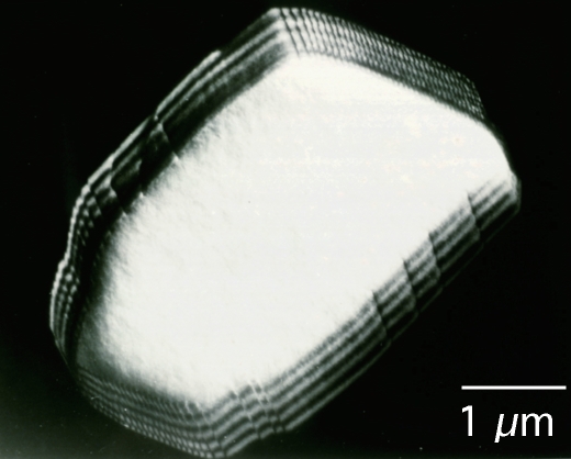
Transmission electron micrograph of tempered martensite in an
Fe-C-Mo steel. The carbides are (Fe,Mo)2C. |
|
|
More on tempered martensite.
Stress-Induced Martensitic Transformation
 |
|
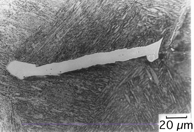
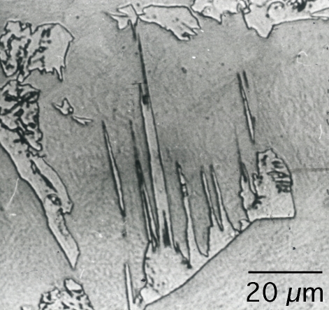
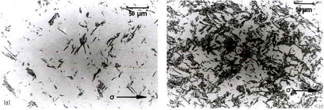
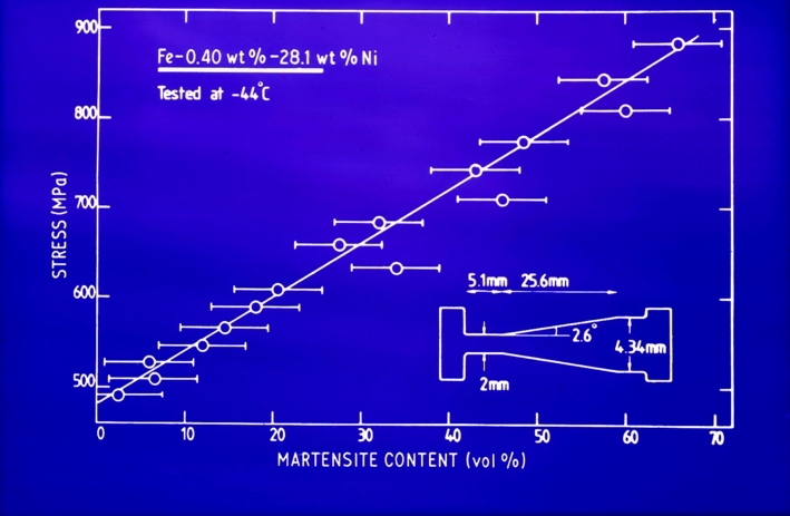
Fe-28Ni-0.4C wt% alloy, which is fully austenitic down to -80oC. The alloy was machined into a tapered tensile test specimen and then pulled to failure at -44oC to induce martensite. The taper produces a gradient of stress, the volume fraction of martensitic transformation increasing with the magnitude of the stress. Notice that the martensite plates are at approximately 45o to the tensile axis; that is they are forming with their habit planes roughly parallel to the planes of maximum shear stress. (a) Region of small stress. (b) Region of large stress, with a correpondingly larger quantity of martensite. |
|
|
 |
|
Fe-28Ni-0.4C wt% alloy, which is fully austenitic down to -80oC. The alloy was machined into a tapered tensile test specimen and then pulled to failure at -44oC to induce martensite. The taper produces a gradient of stress, the volume fraction of martensitic transformation increasing with the magnitude of the stress. |
|
|
Analogy to the Mechanism of Transformation
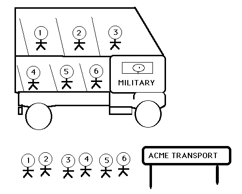
Most solid--state transformations fall into two categories. Displacive
transformations involve a coordinated motion of atoms as the parent lattice is
deformed into that of the product. There is no diffusion and hence there
exists an atomic correspondence between the parent and product phases. A
numbered sequence of atoms is maintained in the product phase. Such
transformations are called military transformations because there
is a disciplined transfer of atoms; the analogy here is that of a highly
disciplined queue of soldiers ordered to board a military bus. The number
sequence of the bus is identical to that in the queue. The soldiers do not have
a choice as to their neighbours (analogous to the solute-trapping
phenomenon). The situation is not at equilibrium.
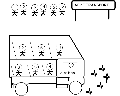
It is the diffusion of atoms that leads to the new crystal
structure during a reconstructive transformation. The flow of
matter is sufficient to avoid strains and solutes may partition between the
parent and product phases. The diffusion--driven flow of matter destroys any
atomic correspondence between the parent and product phases. This is analogous
to a numbered queue of civilians who board the bus in a disorderely manner, so
that the the sequence in the queue bears no resemblance to that in the bus.
A paramilitary is a partly disciplined force. A
paramilitary transformation is one in which interstitial atoms (which
can move rapidly) partition during transformation but the change in crystal
structure is achieved by displacive transformation. This is a common mechanism
of transformation in Fe-C and V-H alloys. The interstitials thus achieve
equilibrium subject to the constraint that the substitutional atoms do not
diffuse.
The images below can be enlarged by clicking on the thumbnails.
 |
 |
 |
|
Military Transformation |
Civilian Transformation |
Paramilitary Transformation |
|
|
Diffusionless Transformation
Substitutional atoms do not diffuse during a displacive
transformation. The pattern in which the atoms are arranged neverthless
changes, leading to a macroscopic change in the shape of the transforming
region. This model illustrates the mechanism of a displacive transformation,
in which there is a coordinated motion of atoms.
Quicktime movies showing the deformation process: Movie 1 (200 kBytes); Movie 2 (26 MBytes).
MPG movies showing the deformation process: Movie 3 (200 kBytes)
 |
 |
|
Starting shape and crystal structure. |
Final shape and crystal structure following a homogeneous
deformation which is a shear. |
|
|
More on martensite.
Deformation due to Bainite Transformation
 |
|
During a displacive transformation, the change in crystal
structure is achieved by a homogeneous deformation of the parent phase. A
sample which is polished flat and then transformed to bainite will
therefore exhibit displacements on the free surface. This atomic-force
microscope image shows the displacements. |
|
|
More on bainite.
Illustration of Grain Growth
 |
 |
|
A glass vial containing a liquid that foams. Shaking results in a
fine foam, which slowly coarsens with time. The coarsening
process is somewhat analogous to grain
growth in solids. |
The same vial, after allowing some time for the foam to coarsen.
The process occurs in order to reduce the surface per unit volume.
|
|
|
Coincidence-Site Lattice (CSL)
A coincidence-site
lattice is constructed by taking two lattices with a common orgin, and
allowing them to pentrate all space; coincidence points are those lattice
points common to the two lattices. This model shown below reproduces this
effect in two dimensions. Two circular grids connected at the centre. The grids
are first aligned to indicate a single crystal. Rotating one with respect to
the other produces a variety of coincidence site lattices, even when the angle
of rotation is large. This model is place on an overhead projector. The effect
can also be seen on movies:
Quicktime movies showing the deformation process: Movie 1 (200 kBytes); Movie 2 (6 MBytes).
MPG movies showing the deformation process: Movie 3 (200 kBytes)
 |
 |
|
The pattern shows coincidence points between the two grids which
are rotated with respect to each other. |
The pattern shows coincidence points between the two grids which
are rotated with respect to each other.
|
|
|
More on interfaces.
Interfacial Dislocations
 |
|
A dark-field transmission electron micrograph of a particle of austenite in ferrite, in a duplex stainless steel (courtesy Peter Southwick). The image illustrates arrays of interfacial dislocations, whose spacing varies with the orientation of the interface plane. |
|
|
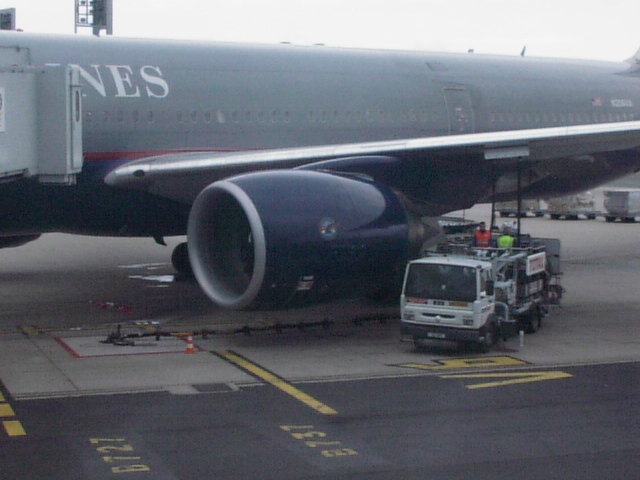
Turbine Blades (Jet Engine)
 |
 |
|
The blades are made out of a nickel-base
superalloy with a microstructure containing about 65% of gamma-prime
precipitates in a polycrystalline gamma matrix. The creep life of the blades is
limited by the grain boundaries which are easy diffusion paths. |
The blade is made out of a nickel-base superalloy with a
microstructure containing about 65% of gamma-prime precipitates in a
polycrystalline gamma matrix. It has been directionally-solidified, resulting
in a columnar grain structure which mitigates grain-boundary induced creep.
|
|
|
 |
 |
|
The blade is made out of a nickel-base superalloy with a
microstructure containing about 65% of gamma-prime precipitates in a
polycrystalline gamma matrix. It has been directionally-solidified, resulting
in a columnar grain structure which mitigates grain-boundary induced creep. |
The blade is made out of a nickel-base superalloy with a
microstructure containing about 65% of gamma-prime precipitates in a
single-crystal gamma matrix. The blade is directionally-solidified via a
spiral selector, which permits only one crystal to grow into the blade.
|
|
|
More on superalloys.
Microstructure of Nickel Superalloys
The microstructure consists of a mixture of about 65% gamma' in a matrix of
gamma. The gamma' is an ordered intermetallic compound Ni3(Al,Ti)
with a cubic-P crystal structure, whereas the gamma is a disordered solid
solution with a cubic-F crystal structure. The gamma and gamma' phase are in
cube-cube orientation with coherent interfaces.
 |
|
(a) Electron diffraction pattern from the gamma (cubic-F) phase.
(b) Electron diffraction pattern from the gamma' (cubic-P) phase. The two
electron diffraction patterns are presented in their correct relative
orientation. (c) Dark field transmission electron micrograph of the gamma phase.
(d) Dark field transmission electron micrograph of the gamma' phase.
|
|
|
More on superalloys.
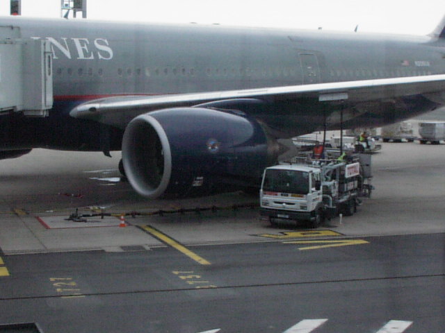
Size of Modern Jet Engine
Microstructure of Aluminium-Lithium Alloys
The microstructure consists of a mixture of delta, an ordered intermetallic
compound Al3Li with a cubic-P crystal structure, whereas the
matrix is a disordered solid solution with a cubic-F crystal structure. The
two phases are in cube-cube orientation with coherent interfaces.
 |
|
Aluminium-lithium alloy with delta-phase particles
|
|
|
Directional Recrystallisation
 |
|
Recrystallisation generally leads to a final microstructure of
equiaxed grains. Recrystallisation in a temperature gradient can lead to a
coarse, columnar grain microstructure. This is common in oxide
dispersion-strengthened nickel superalloys of the type illustrated here.
|
|
|
5.5 GPa Steel Wire
 |
|
This ultra-strong and ductile steel wire is made by severely
deforming a mixture of ferrite and martensite. It is so ductile
that you can tie it into a knot. The bar chart compares the
ductility with other fibres which are much less strong. |
|
|
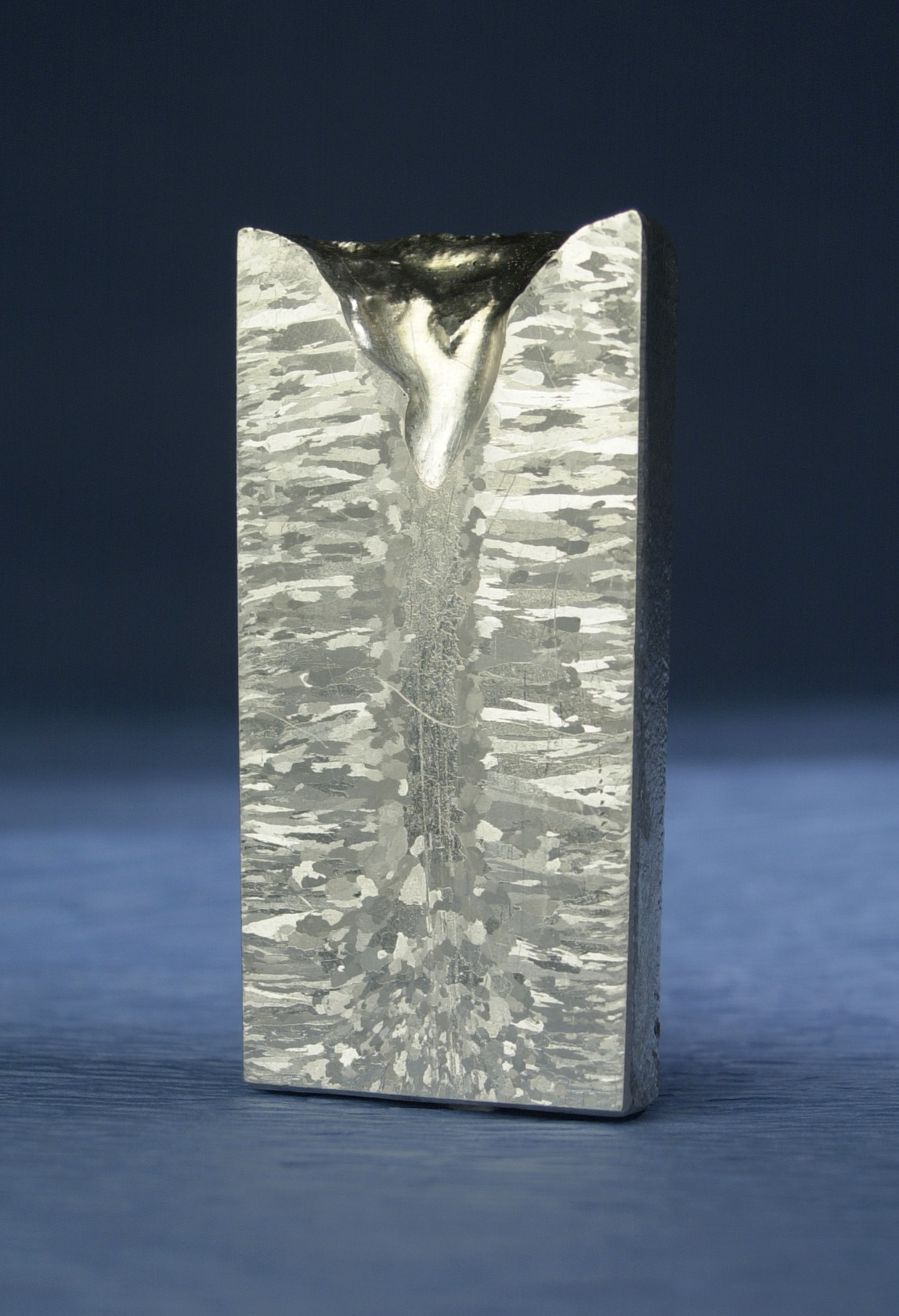
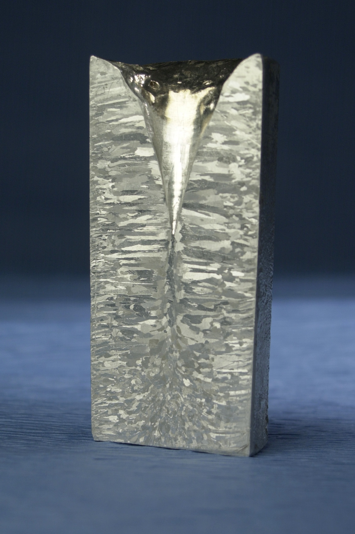
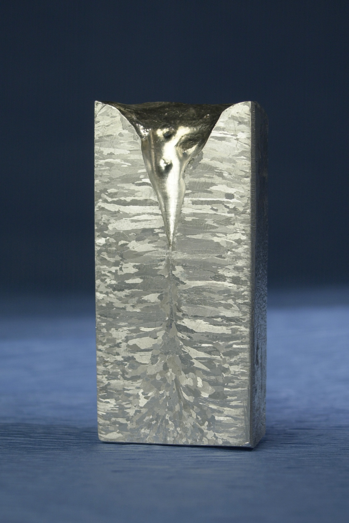
Ingot Solidification Microstructure
This is a macrograph of an aluminium ingot (about 5 cm wide) made by casting commercially pure aluminium in a metal mould. The liquid in contact with the mould wall solidifies relatively rapidly, giving a fine, equiaxed grain structure there. This zone is called the 'chill zone'. The grains then start to grow towards the centre, in the general direction of maximum heat flow, giving a columnar-grain structure. Those grains which have their maximum growth directions most parallel to the heat flow stifle the growth of less favourably oriented grains, leading to a coarsening of the columnar structure as solidification progresses towards the centre.
There is sometimes a region of equiaxed grains in the centre of the ingot, arising from solid particles that form at the liquid surface, or from fragments of metal solidifying from the mould wall.
The central pipe is due to the contraction of the liquid as it solidifies.
Higher resolution images (0.5 Mbytes) of ingots are also available:
More on solidification.


