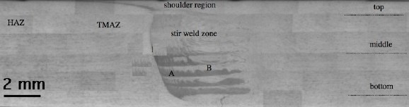

We have seen that there are three zones to consider in the microstructure of a friction stir weld: the heat-affected zone, the thermomechanically affected zone, and the stir zone. The following images illustrate the key features of these regions. They have been provided for teaching purposes by Li Liu and Professor Tsubakino of the University of Hyogo, Japan.
The aluminium alloy concerned is 6061 in the T6 condition, with the chemical composition Al-0.71Si-0.18Fe-0.3Cu-0.07Mn-1.14Mg-0.14Cr-0.03Zn-0.02Ti wt%.
|
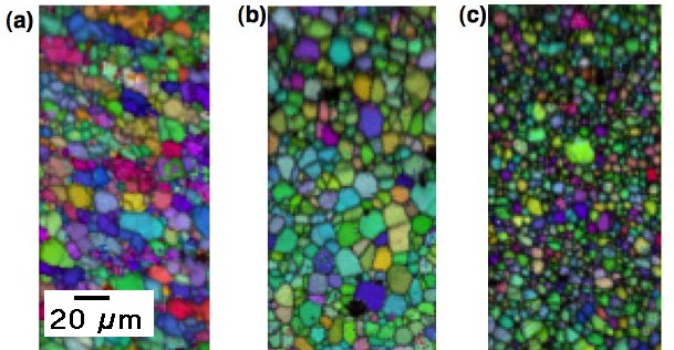
The images below are produced using orientation imaging microscopy; the colours represent different crystallographic orientations. They are from the centre of the weld, with (a) representing the region just below the tool shoulder, (b) the region at the centre of the weld and (c) the bottom of the stir zone.
The grains in region (a) are slightly deformed whereas the other images show equiaxed grains, consistent with a fully recrystallised microstructure. It is evident that the grain structure is not uniform within the stir zone, which undergoes violent deformation whilst hot.
 |
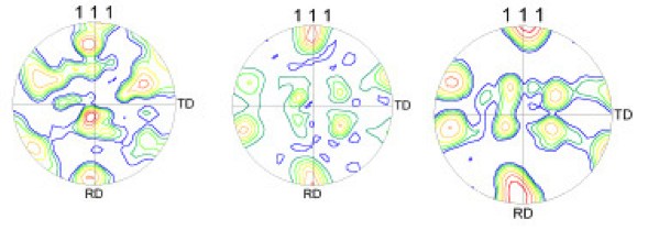
The microstructural variations are due to the heterogeneous nature of the deformation and thermal histories within the stir zone, with dynamic recrystallisation occurring during welding. This also gives rise to crystallographic texture variations, as illustrated in the inverse pole figures shown below (corresponding to the microstructure illustrated above).
 |
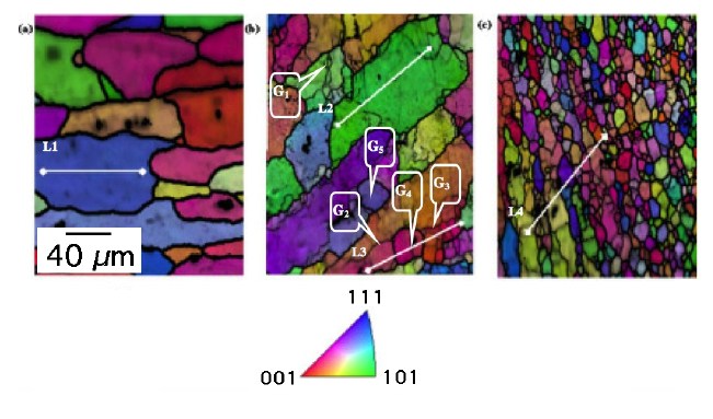
The colours in the images below represent crystallographic orientations; thick black lines represent large crystallographic misorientations between adjacent grains whereas thin black lines represent small misorientations. (a) Heat affected zone; (b) thermomechanically affected zone showing a deformed microstructure; (c) transition from the thermomechanically affected zone to the stir zone.
 |
The images have all been provided for teaching purposes by Li Liu and Professor Harushige Tsubakino of the University of Hyogo, Japan.
| Superalloys | Titanium | Bainite | Martensite | Widmanstätten ferrite |
| Cast iron | Welding | Allotriomorphic ferrite | Movies | Slides |
| Neural Networks | Creep | Mechanicallly Alloyed | Theses |
| PT Group Home | Materials Algorithms |

|

|