
| The following show analysis of complicated electron diffraction patterns containing ferrite, cementite and austenite. A computer program was used to aid analysis. | |
| Ferrite and cementite The ferrite zone is first identified from the ratio of, and angle between, two of the reciprocal lattice vectors. With a knowledge of the lattice parameter of the ferrite, this then allows the camera constant to be calculated. The next step is to calculate the d-spacings of the spots associated with cementite using the camera constant, and similarly analyse the pattern for cementite. The pattern was taken by Lucy Fielding. | |
| Ferrite and cementite The cementite is in Bagaryatski orientation relative to ferrite with [001]cementite parallel to [211] ferrite and [100]cementite parallel to [0 -1 1]ferrite. This can be taken as an indication that the cementite precipitated from the ferrite. The pattern was taken by Lucy Fielding. | |
| Two ferrite crystals and one cementite precipitate. The pattern was taken by Lucy Fielding. | |
| Three ferrite crystals. Notice also the spots arising by double diffraction. The pattern was taken by Ed Pickering. | |
| Two ferrite crystals in twin orientation and one cementite precipitate. The twin patterns are related, for example, by a rotation of 180° about [1 2 -1]. This axis-angle pair can be represented in 24 crystallographically equivalent ways due to cubic symmetry. The pattern was taken by Lucy Fielding. | |
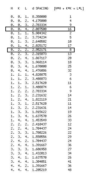
| Diffraction pattern of ferrite and γ-Fe2O3 from a thin foil sample of steel. The oxide forms on the surface and makes a significant contribution to the overall pattern when the foil thickness is reduced. Also available are the crystal structure, caculated electron diffraction pattern and d-spacings for the iron oxide. The pattern was taken by Pei Yan. |
The following images have kindly been provided by Andrew Fairbank who created them for teaching purposes. They are reproduced with permission.
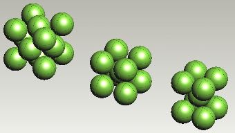
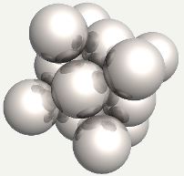
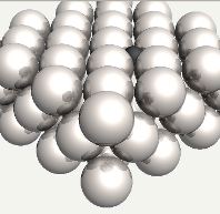
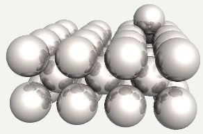
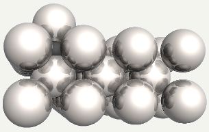
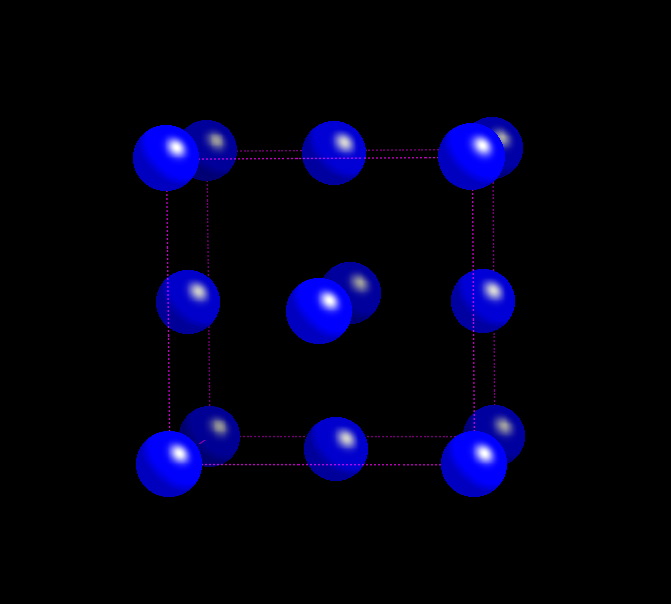
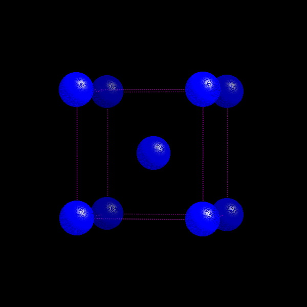
Face-centred cubic, body-centred cubic and body-centred tetragonal arrangements of iron atoms. |
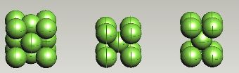
Face-centred cubic, body-centred cubic and body-centred tetragonal arrangements of iron atoms. |
Body-centred cubic and face-centred cubic (alternatively, cubic close-packed) arrangements of iron atoms. |
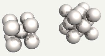
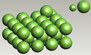
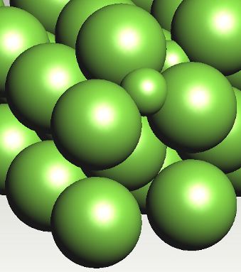
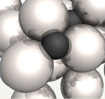
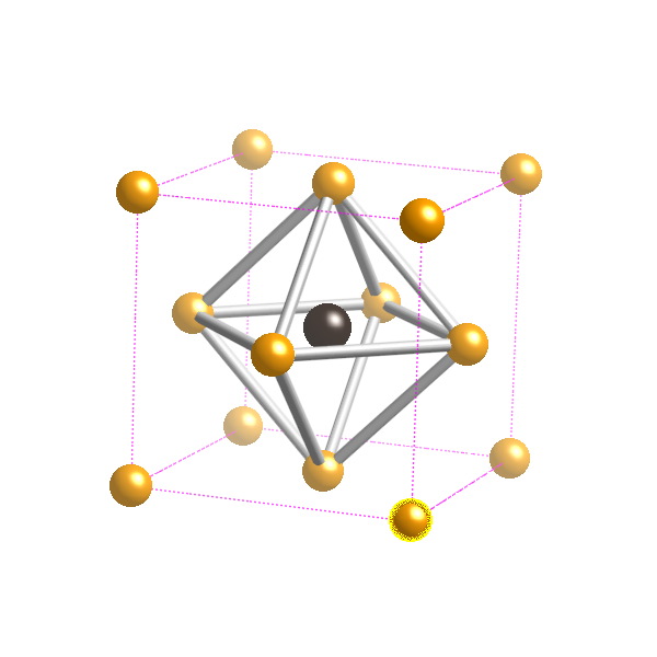
Carbon atom in an octahedral interstice in austenite. |
Carbon atom in an octahedral interstice in austenite, with the face-centering iron atom replaced into position. |
Carbon atom in an octahedral interstice in austenite. |
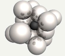
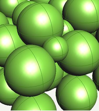
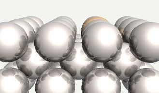
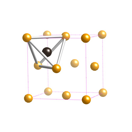
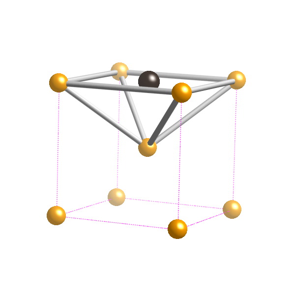
Carbon atom in an octahedral interstice in ferrite. |
Carbon atom in an octahedral interstice in ferrite. |
Carbon atom in an octahedral interstice in ferrite. |
|
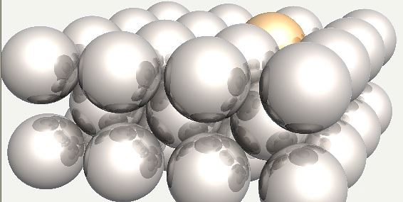
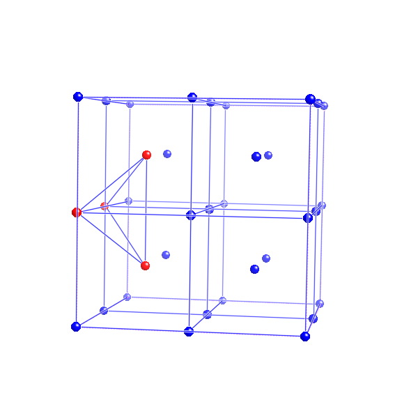
Possible position of carbon atom in a tetrahedral interstice in ferrite. Carbon prefers the octahedral interstices in ferrite. |
Possible position of carbon atom in a tetrahedral interstice in ferrite. |
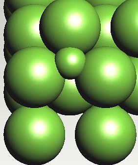
Possible position of carbon atom in a tetrahedral interstice in ferrite. The strain energy is greater when carbon is in a tetrahedral interstice, because the expansion is isotropic, unlike the octahedral case where the strain is tetragonal. |
Possible position of carbon atom in a tetrahedral interstice in ferrite. |
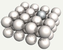
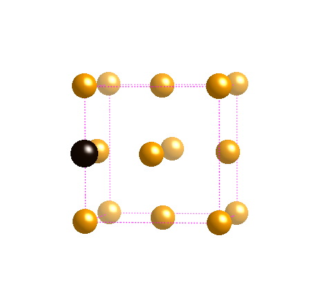
Chromium atom substituted into ferrite. |
Chromium atom substituted into ferrite. |
Silicon atom substituted into ferrite. |
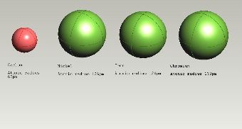
Atomic radii. It has been assumed in the preceding figures that iron has an atomic radius of 124 pm for all the crystal structures. |
| PT Group Home | Materials Algorithms |