![\includegraphics[width=8cm]{mechanism.eps}](img7.png)
|
Materials Science Forum, vols 500-501 (2005) 63-74
H. K. D. H. Bhadeshia
University of Cambridge
Materials Science and Metallurgy
Pembroke Street, Cambridge CB2 3QZ, U. K.
www.phase-trans.msm.cam.ac.uk
The retained austenite is in two forms, the desirable films between the fine plates of ferrite and blocks between different crystallographic variants of bainite, Figure 2.
(a)
![\includegraphics[width=6.2cm]{III.1.eps}](img8.png) (b)
(b)
![\includegraphics[width=6cm]{III.6.eps}](img9.png)
|
A microstructure such as this has advantages. The absence of cementite reduces the chances of cleavage or void nucleation. Unlike martensite, the bainite does not derive its strength from dissolved carbon, which means that it is more resistant to tempering. The heat treatment required to generate the microstructure is simple, and yet has a scale which is less than a millionth of a meter; this cannot usually be achieved without complex processing. Microstructure refinement is an ideal way of optimising both strength and toughness. The films of austenite, intimately dispersed between the ferrite, are buffers to the propagation of cracks. Austenite also is a barrier to the diffusion of hydrogen. Finally, bainitic steels of this kind are cheap - all that is required is sufficient silicon to suppress cementite.
In practice, steels with this apparently utopic microstructure can be brittle [10,11]. The large blocks of austenite between the sheaves of bainite are relatively unstable and transform into high-carbon, untempered martensite under the influence of applied stress, thereby embrittling the steel. How can these islands be eliminated?
(a)
![\includegraphics[width=5.5cm]{tzero2.eps}](img11.png) (b)
(b)
![\includegraphics[width=8.5cm]{tzero.eps}](img12.png)
|
The thermodynamic limit (![]() ) can be manipulated to minimise the troublesome blocks of retained austenite: the substitutional solute content can be altered to shift the
) can be manipulated to minimise the troublesome blocks of retained austenite: the substitutional solute content can be altered to shift the ![]() to higher
to higher ![]() ; the transformation temperature (
; the transformation temperature (![]() ) can be reduced to increase
) can be reduced to increase ![]() ; the average carbon concentration
; the average carbon concentration ![]() of the steel can be reduced to increase the fraction of bainite and hence consume the blocks of austenite. All these cases are expressed in the following equation:
of the steel can be reduced to increase the fraction of bainite and hence consume the blocks of austenite. All these cases are expressed in the following equation:
Notice that the strength of the microstructure depends on its scale - the plates of bainite get finer as the transformation temperature is reduced and the strength of the austenite increased [12,13]. The major component of strength increases with the inverse of the plate thickness.
A design based on the ![]() curve leads to a remarkable improvement in toughness [10,11]. This philosophy has led to the development of a carbide-free bainitic rail, the details of which are described in [14,15], which for bainite can be accounted for as in [16]. The composition of one of the alloys thus designed is
Fe-0.4C-1.5Si-2.0Mn-0.25Mo wt%, the molybdenum being added to prevent prior austenite grain boundary embrittlement due to phosphorus.
curve leads to a remarkable improvement in toughness [10,11]. This philosophy has led to the development of a carbide-free bainitic rail, the details of which are described in [14,15], which for bainite can be accounted for as in [16]. The composition of one of the alloys thus designed is
Fe-0.4C-1.5Si-2.0Mn-0.25Mo wt%, the molybdenum being added to prevent prior austenite grain boundary embrittlement due to phosphorus.
(a)
![\includegraphics[width=7.5cm]{wear.eps}](img18.png) (b)
(b)
![\includegraphics[width=7.5cm]{fatigue.eps}](img19.png)
|
The new rails designed in this manner have superior wear resistance (Fig. 4); unlike any other rail steel, they reduce wear on the wheels [17,18]. Tests have shown dramatic improvements in the rolling contact fatigue life (Fig. 4); whole wheel/rail tests showed crack initiation at two hundred and twenty thousand cycles on traditional pearlitic premium rail, whereas after a million cycles, the new rail steel was crack free when the test was terminated to permit further trials to take place [18]. The carbide-free bainitic rails are weldable using the thermit and flash butt welding processes.
During wear, there is a transfer of material between the contact surfaces, followed by detachment of particles from the transfer layer. The high toughness of the bainitic rail contributes to wear resistance by reducing generation of wear debris [19]. The steels have a softer transfer layer whilst retaining a high bulk hardness. The absence of brittle cementite particles must also contribute to the improved rolling-contact fatigue resistance.
Rail sections are hot-rolled and continuously cooled from the austenitic state. Ordinary rail steels are pearlitic; pearlite colonies, can grow across austenite grain boundaries. In doing so, they destroy the structure that exists at those boundaries and remove them as potential sources for the segregation of impurity atoms such as phosphorus.
By contrast, the coordinated motion of atoms accompanying displacive transformations cannot be sustained across austenite grain boundaries. Therefore, Widmanstätten ferrite, bainite, acicular ferrite and martensite are all confined by austenite grain boundaries. A vestige of the austenite grain boundary![]() therefore remains in the microstructure when the transformations are displacive. This is illustrated schematically in Fig. 5, which shows austenite grain boundaries as hard barriers to martensite (
therefore remains in the microstructure when the transformations are displacive. This is illustrated schematically in Fig. 5, which shows austenite grain boundaries as hard barriers to martensite (![]() ) whereas the allotriomorphs of ferrite (
) whereas the allotriomorphs of ferrite (![]() ) are able to consume the austenite boundaries on which they nucleate, by growing into both of the adjacent grains.
) are able to consume the austenite boundaries on which they nucleate, by growing into both of the adjacent grains.
Impurity segregation to prior austenite grain boundaries can cause intergranular failure at those boundaries. This segregation and associated temper embrittlement occurs during relatively slow cooling through 600![]() C or isothermal holding around that temperature. Fig. 5b shows a Fe-0.26C-2.11Si-2.27Mn-1.59Cr wt% carbide-free bainitic rail steel which has been temper-embrittled by heat treatment at 500
C or isothermal holding around that temperature. Fig. 5b shows a Fe-0.26C-2.11Si-2.27Mn-1.59Cr wt% carbide-free bainitic rail steel which has been temper-embrittled by heat treatment at 500![]() C for 5 h. Failure has occurred at the prior austenite grain boundaries [20].
C for 5 h. Failure has occurred at the prior austenite grain boundaries [20].
Temper embrittlement phenomena are most prominent in strong steels where the applied stress can reach high magnitudes before the onset of plasticity. The problem of temper embrittlement in strong rail-steels became prominent during their development stage; the larger section rails tended to have much lower toughness than those which cooled more rapidly due to their smaller section sizes. It has been assumed that the embrittlement occurs due to phosphorus and it is not practicable to completely remove this element when making rail steels. The alternative is to introduce between 0.2-0.5 wt.% of molybdenum. Molybdenum has been shown to retard temper embrittlement [21,22,23,24]; the effect is greater e vanadium is also added [25]. It was believed at one time that molybdenum scavanges phosphorus, but experiments have failed to confirm this mechanism [26]. Elements such as molybdenum and vanadium must be used cautiously because their addition can lead to an increase in strength, which in turn can trigger a reduction in toughness. Their use must therefore be compensated by appropriate adjustments in the concentrations of other solutes. This is why carbide-free bainitic rail steels contain a combination of 0.15-0.25 wt% of Mo or V. This has allowed temper embrittlment to be controlled without the need for purification.
(a)
![\includegraphics[width=6.5cm]{boundary.eps}](img20.png) (b)
(b)
![\includegraphics[width=8.5cm]{fracture.eps}](img21.png)
|
Typical performance data are illustrated in Fig. 4 and Fig. 6. In pearlitic steels the toughness depends on the pearlite colony size, which is relatively coarse even when the interlamellar spacing is reduced. Thus, although the wear resistance can be improved by refining their microstructure, the toughness is relatively poor. By contrast, the carbide-free microstructure contains fine plates of ferrite mixed with austenite and hence is tough. The high toughness contributes to wear resistance by reducing the rate of production of wear debris [19]. During wear, there is a transfer of material between the contact surfaces, followed by detachment of wear particles from the transfer layer. The bainitic steels have a softer transfer layer whilst retaining a high bulk hardness. The absence of brittle cementite particles must also contribute to the improved rolling-contact fatigue resistance.
(a)
![\includegraphics[width=7.5cm]{toughness.eps}](img22.png) (b)
(b)
![\includegraphics[width=7.5cm]{resistance.eps}](img23.png)
|
Finally, it is worth pointing out that the bainitic rails can be joined using conventional thermit or flash-butt welding techniques. In the latter context, the electrical resistance of the bainitic rails is found to be around 15% greater than pearlitic rails [28], presumably because they contain austenite (Fig. 6) and a larger density of dislocations than pearlitic rails. The rails are now in service, Fig. 7, Table 1.
![\includegraphics[width=12cm]{rail.eps}](img24.png)
|
| Swiss Railways | French National Railways | |
| Composition / wt% | 0.3C 1.25Si 1.55Mn | 0.2C 1.25Si 1.55Mn |
| Composition / wt% | 0.5Cr 0.15Mo | 0.5Cr 0.15V 0.15Mo |
| UTS / MPa | ||
| Elongation / % | ||
| Brinell Hardness | 360-390 | 320-340 |
| Curve Radius / m | 449 | 1140 |
| Cant / mm | 120 | 124 |
| Installation date | November 1999 | December 1998 |
| Traffic type | Freight | Mixed |
| Tonnage / gt per annum |
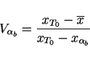
It clearly is possible to eliminate cementite leaving a microstructure of just bainitic ferrite and carbon-enriched retained austenite. Blocks of retained austenite whose size is coarser than desired can be avoided using the ![]() criterion. It has in this way been possible to achieve the highest combination of strength and toughness ever achieved in a bainitic steel, that is, 1600 MPa and
criterion. It has in this way been possible to achieve the highest combination of strength and toughness ever achieved in a bainitic steel, that is, 1600 MPa and
![]() respectively [31,32]. These properties compare with those of the nickel and molybdenum-rich marageing steels at a cost some ninety times cheaper. But how can the strength of carbide-free bainitic steels be improved further?
respectively [31,32]. These properties compare with those of the nickel and molybdenum-rich marageing steels at a cost some ninety times cheaper. But how can the strength of carbide-free bainitic steels be improved further?
It is known that the scale of the bainitic microstructure decreases as the driving force for transformation and the strength of the austenite are increased [12]. One way of simultaneously increasing the driving force and the ![]() strength is to reduce the transformation temperature.
strength is to reduce the transformation temperature.
Figure 8 shows example calculations of the the bainite-start (![]() ) and martensite-start (
) and martensite-start (![]() ) temperatures as a function of the carbon concentration; the calculations have been carried out as in [5,33]. It is clear from these computations that bainite can in principle be produced at ambient temperature (there is in fact no lower limit to the
) temperatures as a function of the carbon concentration; the calculations have been carried out as in [5,33]. It is clear from these computations that bainite can in principle be produced at ambient temperature (there is in fact no lower limit to the ![]() temperature); however, the time would be many centuries to achieve bainite at room temperature in the alloy considered.
temperature); however, the time would be many centuries to achieve bainite at room temperature in the alloy considered.
![\includegraphics[width=16cm]{bs.eps}](img34.png)
|
For practical purposes, a transformation time of say tens of days is reasonable. Experiments consistent with the calculations illustrated in Fig. 8 demonstrated that in a Fe-1.5Si-2Mn-1C wt% steel, bainite can be generated at a temperature as low at 125![]() C, such that the diffusion distance of an iron atom is an inconceivable
C, such that the diffusion distance of an iron atom is an inconceivable ![]() m over the time scale of the experiment!
m over the time scale of the experiment!
What is even more remarkable is that the plates of bainite that grow are only 20-40 nm thick [35,36,37,38]. The slender plates of bainite are dispersed in stable carbon-enriched austenite which buffers the propagation of cracks, Fig. 9. The microstructure has now been characterised, both chemically and spatially to an atomic resolution [39], confirming earlier results [40] that the ferrite retains a large excess concentration of carbon, probably trapped at defects.
(a)
![\includegraphics[width=7.5cm]{microstructure1.eps}](img36.png) (b)
(b)
![\includegraphics[width=7.5cm]{microstructure2.eps}](img37.png)
|
Ultimate tensile strengths of 2500 MPa in tension have been routinely obtained, ductilities in the range 5-30% and toughness in excess of 30-40
![]() . All this in a dirty steel which has been prepared by air melting and hence contains inclusions and pores which would not be there when the steel is made by any respectable manufacturer. The bainite is also the hardest ever achieved, 700 HV. The simple heat treatment involves the austenitisation of a chunk of steel (say 950
. All this in a dirty steel which has been prepared by air melting and hence contains inclusions and pores which would not be there when the steel is made by any respectable manufacturer. The bainite is also the hardest ever achieved, 700 HV. The simple heat treatment involves the austenitisation of a chunk of steel (say 950![]() C), gently transferring into an oven at the low
temperature (say 200
C), gently transferring into an oven at the low
temperature (say 200![]() C) and holding there for ten days or so to generate the microstructure. There is no rapid cooling - residual stresses are avoided. The size of the sample can be large because the time taken to reach 200
C) and holding there for ten days or so to generate the microstructure. There is no rapid cooling - residual stresses are avoided. The size of the sample can be large because the time taken to reach 200![]() C from the austenitisation temperature is much less than that required to initiate bainite. This is a major commercial advantage [41].
C from the austenitisation temperature is much less than that required to initiate bainite. This is a major commercial advantage [41].
It is cheap to heat treat something at temperatures where pizzas are normally cooked. But suppose there is a need for a more rapid process. The transformation can easily be accelerated to occur within hours, by adding solutes which decrease the stability of austenite. There are two choices, aluminium and cobalt, in concentrations less than 2 wt%, have been shown to accelerate the transformation in the manner described. Both are effective, either on their own or in combination [38].
Much of the strength and hardness of the microstructure comes from the very small thickness of the bainite plates. Of the total strength of 2500 MPa, some 1600 MPa can be attributed solely to the fineness of the plates. The residue of strength comes from dislocation forests, the strength of the iron lattice and the resistance to dislocation motion due to solute atoms. Because there are many defects created during the growth of the bainite [5], a large concentration of carbon remains trapped in the bainitic ferrite and refuses to precipitate, probably because it is trapped at defects [40].
Whereas the ordinary tensile strength of the strong bainite is about 2.5 GPa, the strength has been reported to be as high as 10 GPa at the very high strain rates (
![]() ) associated with ballistic tests [42]. The strong bainite has therefore found application in armour. Fig. 11 shows a series of tests conducted using projectiles which are said to be ``one of the more serious battlefield tests" (the details are proprietary). Figs. 11a,b show experiments in which an armour system is tested. A 12 mm thick sample of the bainitic steel is sandwiched between vehicle steel, the whole contained in glass-reinforced plastic. In ordinary armour the projectile would have penetrated completely whereas the bainite has prevented this; the steel did however crack. By reducing the hardness (transforming at a higher temperature), it was possible for the armour to support multiple hits (Fig. 11c without being incorporated in an armour-system.
) associated with ballistic tests [42]. The strong bainite has therefore found application in armour. Fig. 11 shows a series of tests conducted using projectiles which are said to be ``one of the more serious battlefield tests" (the details are proprietary). Figs. 11a,b show experiments in which an armour system is tested. A 12 mm thick sample of the bainitic steel is sandwiched between vehicle steel, the whole contained in glass-reinforced plastic. In ordinary armour the projectile would have penetrated completely whereas the bainite has prevented this; the steel did however crack. By reducing the hardness (transforming at a higher temperature), it was possible for the armour to support multiple hits (Fig. 11c without being incorporated in an armour-system.
![\includegraphics[width=6cm]{hammond.eps}](img40.png)
|
The ballistic mass efficiency BME of an armour is defined as
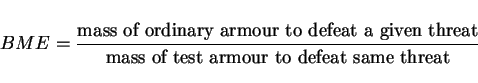 |
(2) |
(a)
![\includegraphics[width=5cm]{armour1.eps}](img42.png) (b)
(b)
![\includegraphics[width=5cm]{armour2.eps}](img43.png)
(c) ![\includegraphics[width=5cm]{armour3.eps}](img44.png) (d)
(d)
![\includegraphics[width=8cm]{armour4.eps}](img45.png)
|
Many aspects of bainite can now be calculated without recourse to experiments, as a function of the chemical composition and heat treatment. This is particularly so for silicon-rich steels in which the upper bainite forms without the precipitation of cementite. Alloys produced using the theory have been demonstrated to exhibit some quite remarkable properties at low cost. The future of these alloys is promising.
I am grateful to Prof. Jose Maria Rodriguez-Ibabe and the Conference organisers for their support.