
|
|
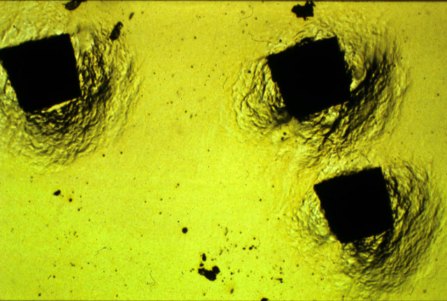
An image of three hardness indents in bright field illumination. The surface of the specimen is normal to the optic axis of the microscope and white light is used to illuminate the sample. Beams reflected back in a direction which is nearly antiparallel to the incident beam form the image. Hence, inclined surfaces (such as those in the indentations) appear dark since they do not reflect the incident beam back into the microscope to form the image. |
|
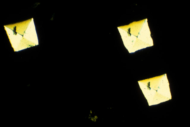
Corresponding image of three hardness indents in dark field illumination. Beams reflected at a large angle to the optic axis are collected to form the image. Inclined surfaces therefore appear bright. |
|
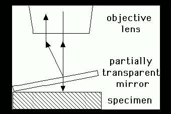
Interference microscopy is used quantitatively to detect changes in surface height. The partially transparent mirror splits the incident beam in two. The two beams then interfere to produce fringes whose spacing is equivalent to a height change of half the wavelength of the light used. The picture shows just two beams interfering. This gives a sinusoidal profile to the variation in intensity between fringes, which can make it difficult to locate the precise position of the fringe. The fringes can be sharpened up using multiple beam interferometry, as in the Tolansky image presented below. |
|
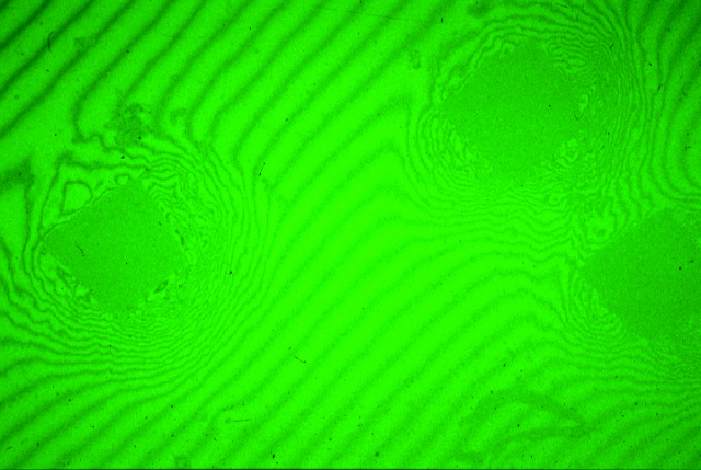
Tolansky interference contrast image of the three hardness indentations. The fringes are in effect contour maps, being more closely spaced at steeply inclined planes. Note that monochromatic (green) light is used for Tolansky interference microscopy. |
|
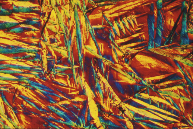
In this qualitative technique the different colours represent a variety of inclinations. The sample shows the surface displacements produced when austenite in steel is transformed to martensite. |
|
|
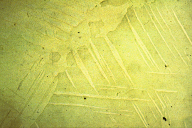
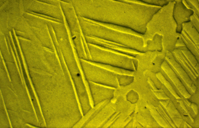
The relief on an etched metallographic specimen can be enhanced using oblique illumination. The image on the left uses incident illumination, whereas the illumination is oblique for that on the right.
| Envelope | Coefficients | Filling welds | Hot | Delta |
| Satoh | Fields | Piping | European welds | Poles |
| Mixed | Creep | Extraordinary ductility | Problems | Mechanical stabilisation |
| Superalloys | Titanium | Bainite | Martensite | Widmanstätten ferrite |
| Cast iron | Welding | Allotriomorphic ferrite | Movies | Slides |
| Neural Networks | Creep | Mechanicallly Alloyed | Theses | Retained Austenite |
| PT Group Home | Materials Algorithms |